


IMPORTANT SAFETY NOTICE
Appropriate service methods and proper repair procedures are essential for the safe, reliable operation of all running gear as well as the personal safety of the individual doing the work. This manual provides general directions for performing service and repair work with tested, effective techniques. Following these guidelines will help assure reliability. There are numerous variations in procedures, techniques, tools, and parts for servicing axles, as well as in the skill of the individual doing the repair.This manual cannot anticipate all such variations and provide advice or cautions as to each. Accordingly, anyone who diverts from this manual must first establish that they neither compromise their personal safety nor the vehicle integrity by their choice of methods, tools, or parts.
- WHEEL NUT TORQUE: at 10, 25, and 50 miles
- BRAKE ADJUSTMENT: at 200 and 3000 miles
- TIRE PRESSURE: to manufacturer requirements
- Elevate and support the trailer unit per manufacturers’ instructions.
- Remove the wheel assembly.
- Remove the grease cap by carefully prying progressively around the flange of the cap.
- Remove the cotter pin from the spindle nut or in the case of Easy Lube, bend the tang washer to the free position.
- Unscrew the spindle nut counter clockwise and remove the D-washer.
- Remove the hub from the spindle, be careful to not let the outer bearing fall out.
- 7” Brake Drum – 7.090”
- 10” Brake Drum – 10.090”
- 12” Brake Drum – 12.090”
- Place the hub on a flat work surface with the cup being replaced on the bottom side.
- Using a brass drift punch, carefully tap around the small diameter end of the cup to drive it out.
- After cleaning the hub bore area, replace the cup by tapping it in with the brass drift punch. Be sure the cup is seated all the way up against the retaining shoulder in the hub.
Axle Information
| Axle Capacity | Spindle Diameter | Inner Bearing/Cup | Outer Bearing/Cup | Seal Number |
|---|---|---|---|---|
| 2,200 LBS | 1-1/16” | 44649 / 44610 | 44649 / 44610 | 15192TBG |
| 3,500 LBS | 1-1/16” - 1-3/8” | 68149 / 68111 | 44649 / 44610 | 171255TBG |
| 6,000 LBS | 1-1/4” - 1-3/4” | 25580 / 25520 | 15123 / 15245 | 22333TBG |
| 7,000 LBS | 1-1/4” - 1-3/4” | 25580 / 25520 | 14125 / 14279 | 22333TBG |
- Place a quantity of grease into the palm of your hand.
- Press a section of the widest end of the bearing into the outer edge of the grease pile closest to the thumb, forcing grease into the interior of the bearing.
- Repeat this while rotating the bearing from roller to roller.
- Continue this process until the entire bearing is completely filled with grease.
- Before installing, apply a light coat of grease on the bearing cup.
- Pry the seal out of the hub with a screwdriver. Never drive the seal out with the inner bearing as you may cause damage to the bearing.
- Apply sealant to the outside of the new seal.
- Tap the new seal into place using a clean wood block.
- After placing the hub, bearing, washers, and spindle nut back on the axle spindle in reverse order as detailed in the previous section on hub removal, rotate the hub assembly slowly while tightening the spindle nut to approximately 50 lbs/ft.
- Loosen the spindle nut to remove the torque. Do not rotate the hub.
- Finger tighten the spindle nut until snug.
- Back the spindle nut out slightly until the first castellation lines up with the cotter keyhole and insert the cotter pin (or locking tang in case of Easy Lube).
- Bend the cotter pin legs over to secure the nut (or locking tang washer in case of Easy Lube).
- Castle Nut should be free to move with only restraint being the cotter pin (or locking Tab)
Approved Lubricants:
- Mobil Oil – Mobil grease HP
- Standard – Renox MP
- Kendall Refining Co. – Kendall L-427
- Ashland Oil Co. – Valvoline Val-plex EP Grease
If your axle is equipped with the EASY Lube feature, the bearing can be periodically lubricated without removing the hub from the axle. This feature consists of axle spindles that have been specially drilled and fitted with a grease zerk in the ends. When grease is pumped into the zerk, it is channeled to the inner bearing then flows back to the outer bearing and eventually back out the grease cap hole.
The procedure is as follows:
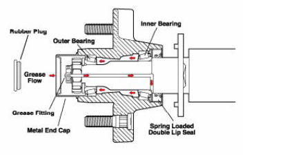
- Remove the rubber plug from the end of the grease cap.
- Place a standard grease gun onto the grease zerk located in the end of the spindle. Make sure the grease gun is fully engaged on the fitting.
- Pump grease into the zerk. The old, displaced grease will begin to flow back out of the cap around the grease gun nozzle.
- When the new, clean grease is observed, remove the grease gun, wipe off any excess, and replace the rubber plug in the cap.
NOTE: The Easy Lube feature is designed to allow immersion. Axles not equipped with Easy Lube are not designed for immersion and bearings should be repacked after each immersion.
NOTE: Even with the Easy Lube feature, periodic inspection and repacking must be done every 6 months or 6,000 miles. Do not pack hub full of grease. Excessive grease may leak into brake drums causing brake failures.
- Attach the axle to the trailer.
- Dampen the effects of road shock.
- Provide stability to the trailer
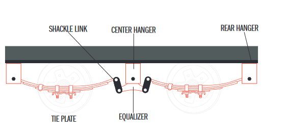
Double eye springs have eyes formed in each end of the spring and are attached to the trailer as follows:
- The front spring eye is attached directly to the front hanger with a bolt and nut.
- The rear spring eye is attached to a pair of shackle links, which is attached to either a center equalizer or a rear hanger.
The articulation of this suspension occurs when the spring becomes loaded and consequently lengthens. The double pivot action of the shackle links accommodates this articulation and allows the system to move freely. In multiple axle installations, the action is the same, but with the additional movement of the equalizer assembly that serves to transfer instantaneous loads from one axle to another, in an effort to “equalize” the load between the axles.
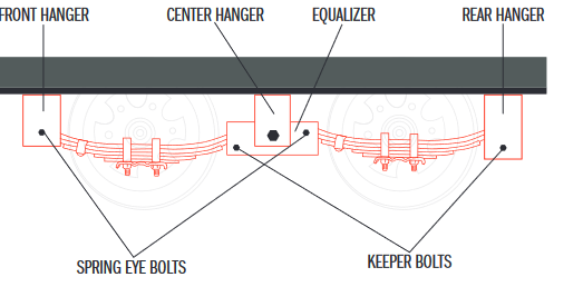
Slipper springs have an eye formed in one end only with the other end formed into a reverse curve. The attachment of these springs is as follows:
- The front eye is attached directly into the front hanger with a nut and a bolt.
- The rear end of the spring is captured in the rear hanger or equalizer with a “keeper bolt” that prevents the spring from coming out when the trailer is jacked up for service.
The articulation of this suspension occurs when the rear end of each slipper spring slides against the wear surfaces provided in the rear hangers or equalizers. This suspension is also available in single and multiple axle configurations.
| Item | Minimum Torque (LBS/FT) | Maximum Torque (LBS/FT) |
|---|---|---|
| 1/2” U-Bolt | 45 | 60 |
| Shoulder Type | 30 | 50 |
| Shackle Bolt | 30 | 50 |
| Spring Eye Bolt | Snug fit only. Parts must rotate freely. Locking nuts or cotter pins are provided to retain nut/bolt assembly. | |
| Equalizer | Snug fit only. Parts must rotate freely. Locking nuts or cotter pins are provided to retain nut/bolt assembly. | |
Worn spring eye bushings, sagging springs, or broken springs should be replaced using the following method:
- Support the trailer with the wheels just off the ground. Follow the trailer manufacturer’s recommendations for lifting and supporting the unit. Do not lift or place supports on any part of the suspension system.
- After the unit is properly supported, place a suitable block under the axle tube near the end to be repaired. This block is to support the weight of the axle only so that suspension components can be removed.
- Disassemble the U-bolts, nuts, and tie plates.
- Remove the spring eye bolts and spring, and place them on a suitable work surface.
- If the spring eye bushings need to be replaced, drive out the old bushing using a suitable drift punch.
- Drive the new bushing into the spring eye using a piloted drift punch or a close-fitting bolt inserted through the bushing.
- Reinstall replaced components in reverse order.
NOTE: For multiple axle units, the weight of each axle must be supported as outlined in step 2 before disassembly of any component of the suspension system.
If the equalizer or equalizer bushing must be replaced, follow the instructions above for lifting and supporting the trailer unit and then proceed as follows:
- With both axles blocked up, remove the spring eye bolt, shackle bolt, and equalizer bolt from the equalizer to be repaired or replaced.
- Take the equalizer to a suitable work surface and remove the worn bushings using a drift punch.
- Drive the new bushing into place using a piloted drift punch or a close-fitting bolt through the bushing.
- Reassemble in reverse order.
If the equalizer or equalizer bushing must be replaced, follow the instructions above for lifting and supporting the trailer unit and then proceed as follows:
- With both axles blocked up, remove the spring eye bolt, shackle bolt, and equalizer bolt from the equalizer to be repaired or replaced.
- Take the equalizer to a suitable work surface and remove the worn bushings using a drift punch
- Drive the new bushing into place using a piloted drift punch or a close fitting bolt through the bushing
- Reassemble in reverse order.
All of the pivot points on your suspension system have been fitted with anti-friction bearing materials which do not require routine lubrication. However, when otherwise servicing the unit, these pivot points may be lubricated if you so desire. Except for periodic inspection of the fasteners used to attach the RUBBER TORSION axle to the vehicle frame, no other suspension maintenance is required on RUBBER TORSION axles. They are, of course, subject to the maintenance and inspection procedures regarding brakes, hubs, bearings, wheels, and tires as outlined in this manual.
It is extremely important to apply and maintain proper wheel mounting torque on your trailer axle. Torque is a measure of the amount of tightening applied to a fastener (nut or bolt) and is expressed as length times force. For example, a force of 90 pounds applied at the end of a wrench one foot long will yield 90 LBS/FT of torque. Torque wrenches are the best method to ensure the correct amount of torque is being applied to a fastener.
NOTE: Wheel nuts or bolts must be applied and maintained at the proper torque levels to prevent loose wheels, broken studs, and possible dangerous separation of wheels from your axle.
Be sure to use only fasteners matched to the cone angle of your wheel (usually 60 or 90 degrees). The proper procedure for attaching your wheels is as follows:
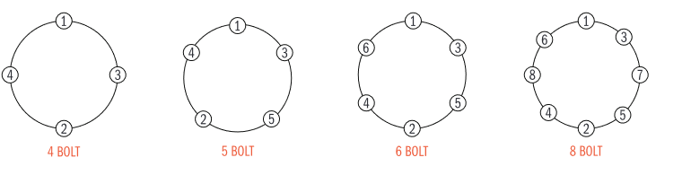
- Start all bolts or nuts by hand to prevent cross-threading.
- Tighten bolts or nuts in the following sequence.
- The tightening of the fasteners should be done in stages. Following the recommended sequence, tighten fasteners per the wheel torque chart.
- Wheel nuts/ bolts should be torqued before the first road use and after each wheel removal. Check and re-torque after the first 10 miles, 25 miles, and again at 50 miles. Check periodically thereafter
| Wheel Size | 1st Stage (LBS/FT) | 2nd Stage (LBS/FT) | 3rd Stage (LBS/FT) |
|---|---|---|---|
| 12” | 20-25 | 35-40 | 50-75 |
| 13” | 20-25 | 25-40 | 50-75 |
| 14” | 20-25 | 50-60 | 90-120 |
| 15” | 20-25 | 50-60 | 90-120 |
| 16” | 20-25 | 50-60 | 90-120 |
CAUTION: Incorrect wheel nuts or improperly tightened wheel nuts can cause the wheel to become loose and even come off. Be sure to use the correct wheel nuts
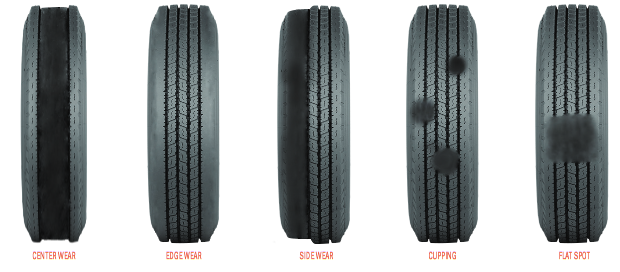
| Wear Pattern | Cause | Action |
|---|---|---|
| Center Wear | Over inflation | Adjust pressure to particular load per tire catalog |
| Edge Wear | Under inflation | Adjust pressure to particular load per tire catalog |
| Side Wear | Loss of camber or overloading | Make sure load doesn’t exceed load rating. Align at alignment shop |
| Cupping | Out of balance | Check bearing adjustment and balance tires |
| Flat Spots | Wheel lockup & tire skidding | Avoid sudden stops and adjust brakes |
- Jack up the trailer and place jack stands under the trailer frame so that the weight will be off the tires. Follow trailer manufacturer’s guidelines to lift and support the unit. Never jack up or place jack stands on the axle tube or on the equalizers.
- Lubricate mechanical parts such as the hitch and the suspension parts that are exposed to the weather.
- Boat trailer axles are subject to repeated immersion. Before storing, remove brake drums and inspect bearings. Clean and lubricate.
Before removing trailer from jack stands:
- Remove all wheels and hubs or brake drums. Note which spindle and brake that the drum was removed from so that it can be reinstalled in the same location.
- Inspect suspension for wear.
- Check tightness of the hanger bolts, shackle bolt, and U-bolt nuts per recommended torque values.
- Check brake linings, brake drums, and armature faces for excessive wear or scoring.
- Lubricate all moving brake parts.
- Remove any rust from the surface of drums with fine emery paper.
- Inspect grease seals for wear or nicks. Replace if necessary.
- Lubricate hub bearings.
- Reinstall hubs and adjust bearings per instructions on page 5.
- Mount and tighten wheel nuts per instructions on page 9.
First 200 miles – Brake adjustment.
3,000 miles or 3 months – Brake adjustment, torque on wheel nuts, and tire inspection for wear.
6,000 miles or 6 months – Inspect brake magnets for wear, inspect suspension parts for wear, and grease bearings.
12,000 miles or 12 months – Inspect brake lining wear, brake cylinder leaks, brake lines, grease bearings. Check hub for wear, inspect grease seal, and inspect springs for any wear or loss of arch. Remove any rust from the surface of drums with fine emery paper.